Nodes are becoming a larger part of Blender and the worst part of nodes is they can become a confusing mess. Here’s everything you need to know about how to organize nodes in Blender.
This guide will cover the following six ways to organize nodes:
This page may contain affiliate links which pay me a commission if used to make a purchase. As an Amazon Associate, I earn from qualifying purchases.
Collapse Nodes & Hide Unused Sockets
The first way to clean up a messy node tree in Blender is to collapse nodes and/or hide unused sockets. These are two different things. On every node there is an arrow next to its label that toggles whether the node is collapsed or expanded.
To collapse or expand a node in Blender, toggle the arrow to the left of the node’s label.
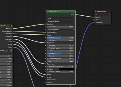
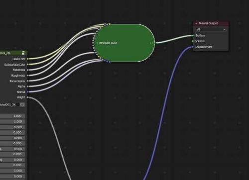
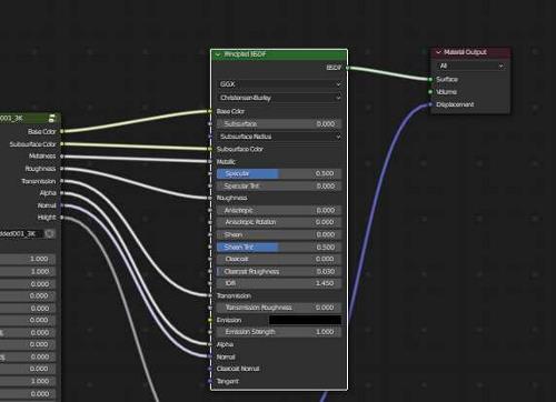
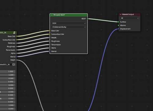
Collapsing a node will entirely hide all inputs and values of the node. An alternative is to hide only the unused sockets. This is especially useful for large nodes like the Principled BSDF Shader which have many sockets which may go unused.
To hide unused sockets of a node in Blender, select the node and use the shortcut “Ctrl + H.” To show the hidden sockets, repeat the shortcut with the node selected.
Below is the difference between a full Principled BSDF Shader vs when the unused sockets are hidden.
Labeling Individual Nodes
We can give each individual node in Blender a unique name, label and color. This will work in all node editors (shader editor, geometry nodes, etc).
With a node selected, open the sidebar menu in the node editor by pressing “N” on the keyboard. The sidebar will expand on the right side of the editor.
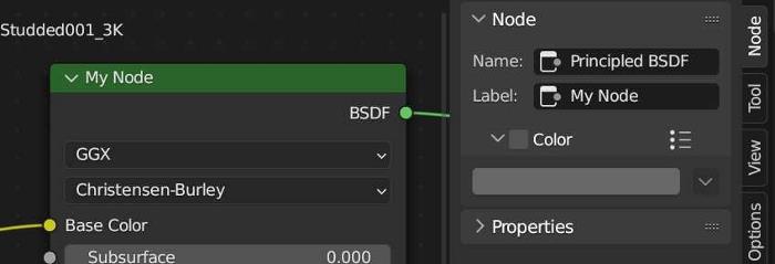
We can give the individual node a custom name. This may be helpful in certain situations, but the name is not what appears on the node itself. What’s more useful is giving the node a custom label. The label will appear at the top of the node, replacing the default label.
Assign Color to a Node
Below the name and label options is a check box to give the node a custom color. Checking the box will activate a color picker. The color chosen will be the background color of the selected node.
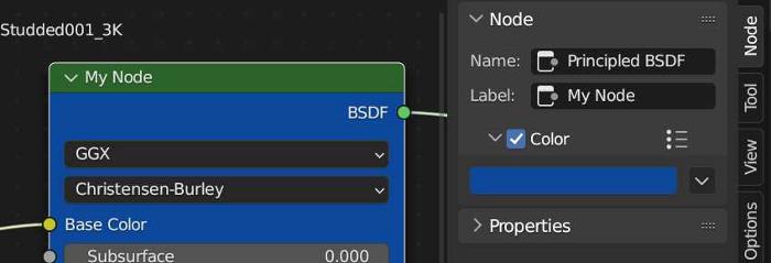
Node Color Presets
If we have a certain color we wish to apply to nodes often, we can save it as a preset. To do this, choose the color and then click the preset icon to the right of the color checkbox. Give the preset a name and press the plus icon. It will now be saved for use with future nodes.
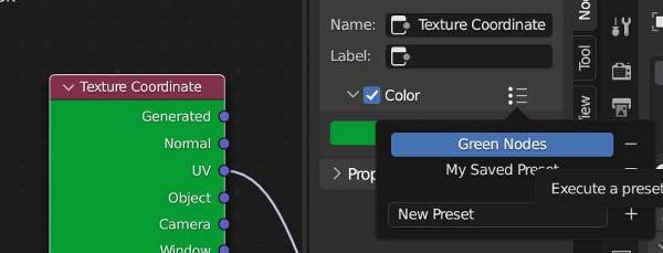
To use a saved preset later, select a node. Activate the color checkbox but this time select the preset tab and choose from the saved presets. It will populate the color for the selected node.
Reset Node Label and Color
Above all of these settings is a reset button. To reset the name, label and color of an individual node, open the sidebar menu in the node editor by pressing “N.” Then press the “Reset Node” button to return the node to its default name, label and color.
Using Frames to Organize Nodes
If we have a complex node setup, frames are one of the first things we may consider using for organization. Frames are visual containers to hold nodes within the editor. They don’t contribute or restrict any functionality of the node tree.
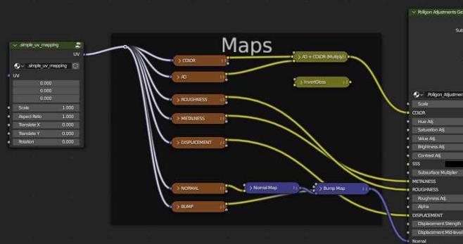
Frames can be given labels to let you or other users know what the included nodes contribute to the final output. Frames can be colorized to help them stand out in a complicated node tree.
To group nodes using frames in Blender, select the nodes you want to group. Then, press Control + J to create a frame around them.
Once nodes have been placed into a frame, the frame will dynamically expand and contract if you move the included nodes. This ensures the nodes are always contained within the frame.
We can select the frame to move it by clicking on the border of the frame.
To remove a node from a frame, select the node and press “Alt + P.”
To delete a node frame, select the frame and press “X” on the keyboard. The frame will be deleted but the nodes inside the frame will not be affected.
Assigning Labels to Node Frames
After creating a node frame in Blender, we can select it by clicking near the edge of the frame. By default, it will be a black frame with no label but we can change this.
Select the frame and press “N” on the keyboard to toggle open the sidebar menu in the editor. In the sidebar, we will see name, label and color options for the selected frame.

The name will (obviously) name the frame but the name is not what appears on the top of the frame. The more helpful setting in most cases is the “label.” When we type something into the “label” field, it will appear at the top of the frame.
This can be useful to remember what the grouped nodes in the frame are contributing to the node tree.
Assigning Color to Node Frames
A good visual aid for organizing nodes is to assign different colors to node frames. To add a color, select a frame and make sure the sidebar is open in the shader editor. If it’s not, press “N” while hovering in the shader editor to open it.

Below the name and label options is a checkmark for “Color.” Check it on and expand the arrow to open more options. A color picker will display which can be used to give the frame a custom color.
Using Node Groups to Organize Nodes
Frames are great for organizing nodes that you want to see at all times. But often, we want to condense nodes to make our node trees less complex.
Node groups allow us to combine multiple nodes into a single node and choose which settings can be adjusted from the condensed node. This results in a completely customizable node.
To create a node group in Blender, select nodes we wish to combine. Press “Control + G” on the keyboard to create the node group. Press “Tab” to enter and exit the node group when it is selected.
When we create a node group, we are taken “inside” the node group and will only see the selected nodes. Node groups act similar to objects in how we edit them.
Pressing tab will take us into something similar to “Edit Mode” where we see the nodes inside the group and edit the group. Pressing tab will exit the node and take you back to the main shader editor setup.
Creating Node Group Inputs
When combining a series of nodes, there may be several inputs of different nodes we want to be adjustable without entering the node group. We can create custom inputs for the node group.
Inside the node group will be a Group Input Node. It will begin with one output socket on its right side that can be connected to any input socket within the group.
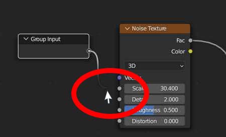
Once the first socket of the group input node is connected to a node, a new socket will appear. We can add as many group inputs as we want.
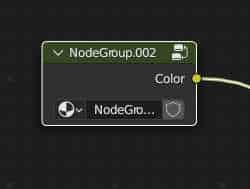
To illustrate this, here is an example of a node group with no inputs added to the group.
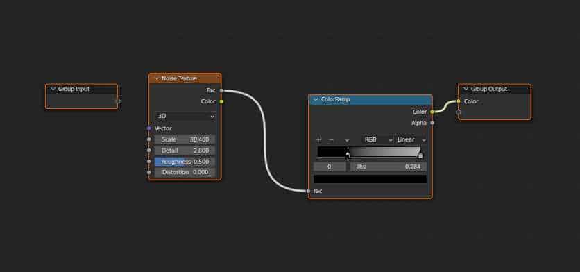
And here, two inputs have been added (scale and detail) to the node group. These inputs are now adjustable from the custom group node.
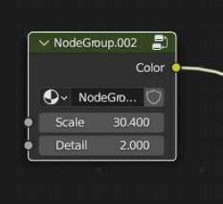
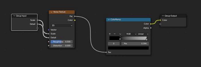
The nodes can continue to be customized as much as we want. We can connect input sockets to any node within the group. Only the identified inputs will be adjustable from the custom group node.
Node Group Labels & Colors
Similar to individual nodes, we can give a node group a custom label and color. With a node group selected, press “N” on the keyboard to toggle open the sidebar menu. Select the tab labeled “Node.”

We can give the node group a custom label and change the color of the node.
Ungrouping Nodes
To ungroup a node group, we first select it. Then right click in the node editor and choose “Ungroup.” We can also use the shortcut “Ctrl + Alt + G.”
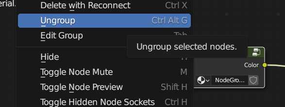
Find more information about node groups in the Blender Manual documentation on node groups.
Reroute Nodes
Sometimes the best way to better organize a node tree is to organize the noodles connecting the nodes. One way to do this is to use a reroute node.
These small nodes don’t contribute anything to the node tree, but are used to reposition the noodle connections between nodes.

To add a reroute node in Blender, press “Shift + A” and search for the node called “reroute.” Drag the new node onto a node connection or create new connections to the node.
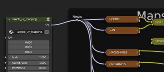
A reroute node can only have one input connection but can have many outputs. Reroute nodes can be labeled like other nodes and the label will appear just above the node in the shader editor.
Adjusting Node Connector “Noodle” Curving
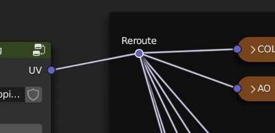
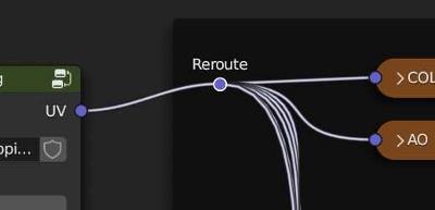
The connections between nodes in any of Blender’s node editors are known as “noodles.” The curviness of a noodle (or how straight the connections between nodes are) can be adjusted in the Blender User Preferences.
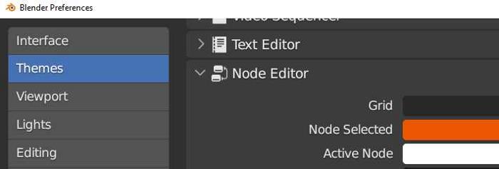
To adjust noodle curving in Blender, go to Preferences > Themes > Node Editor. Scroll down to the “Noodle Curving” setting. A higher setting will make node links more curvy. A lower setting will make the links straighter.

The noodle curving setting can be set between zero and ten. At zero, the noodles will be straight lines from an output to an input.
An Add-On to Preview Nodes
An add-on I’ve been using for a while to visualize node preview images is called Node Preview. It’s available on Blender Market. It’s simple and works. Learn more about the Node Preview add-on here.
Get Brandon’s Newsletter
By submitting, you agree to receive periodic e-mails from me. You can unsubscribe at any time.
