This Blender 3D tutorial covers a technique to add an animated disintegration effect to any material within Blender’s shader editor. We will cover procedurally dissolving an object and animating the effect. Here’s how to disintegrate an object in Blender 3D.
This page may contain affiliate links which pay me a commission if used to make a purchase. As an Amazon Associate, I earn from qualifying purchases.
The original tutorial is a video from my YouTube channel and this page serves as a companion guide. I’ve detailed each step of creating the procedural disintegration effect here. Watch the following video or keep reading for detailed step-by-step instructions.
If you’re extremely new to Blender, I also recommend watching my two-part introduction to material shading tutorial.
Getting Started: Base Material
The procedural disintegration effect is added to an existing material. It can work with almost any material that uses a Principled BSDF Shader, as long as the material doesn’t use emission from the Principled Shader (this is technically possible, but more complex).
Ensure the object you want to dissolve has only one material assigned to it (or do this to each assigned material). For my demonstration, I’ll be using the Eevee render engine but this will also work in Cycles.
Ensure the “Use Nodes” button is activated for the selected material.
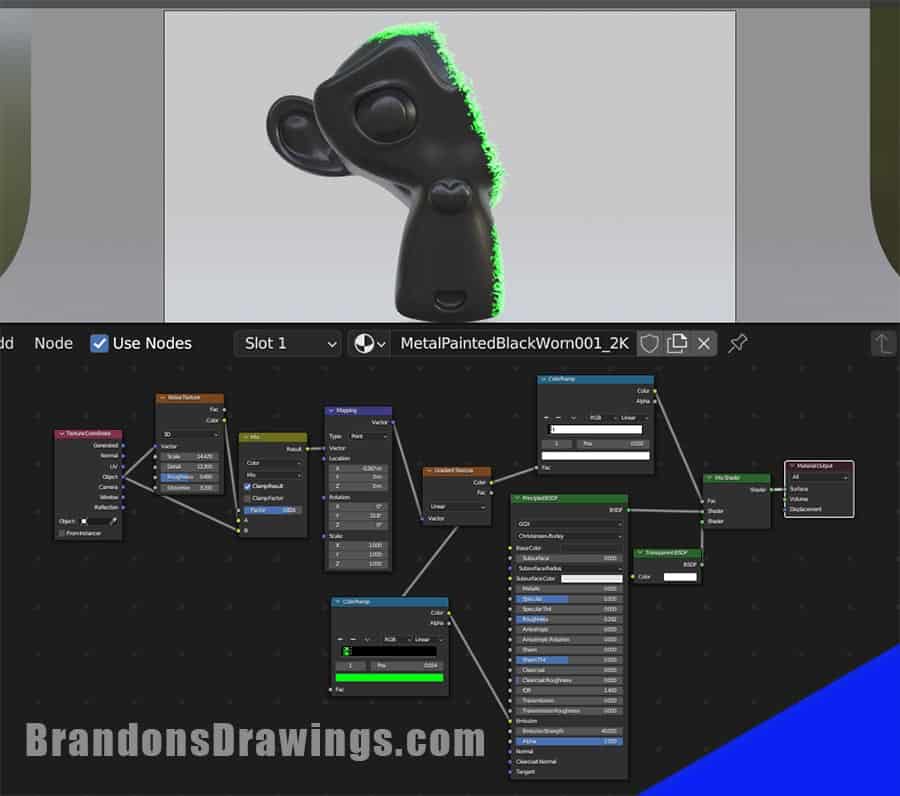
Most of the nodes for this effect will branch off between the Principled BSDF’s output and the final material output node.
Step 1: Add Mix Shader
The first step is to add a Mix Shader between the Principled BSDF and the Output Node. Use the “Mix Shader” and not the “Mix” node.
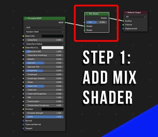
This allows us to combine our base material with a Transparent Shader in the next step.
Step 2: Add Transparent Shader
The second step is to add a Transparent BSDF Shader and plug it into the second input node of the Mix Shader. In a related Blender article, I thoroughly explain the use of transparency in Blender.
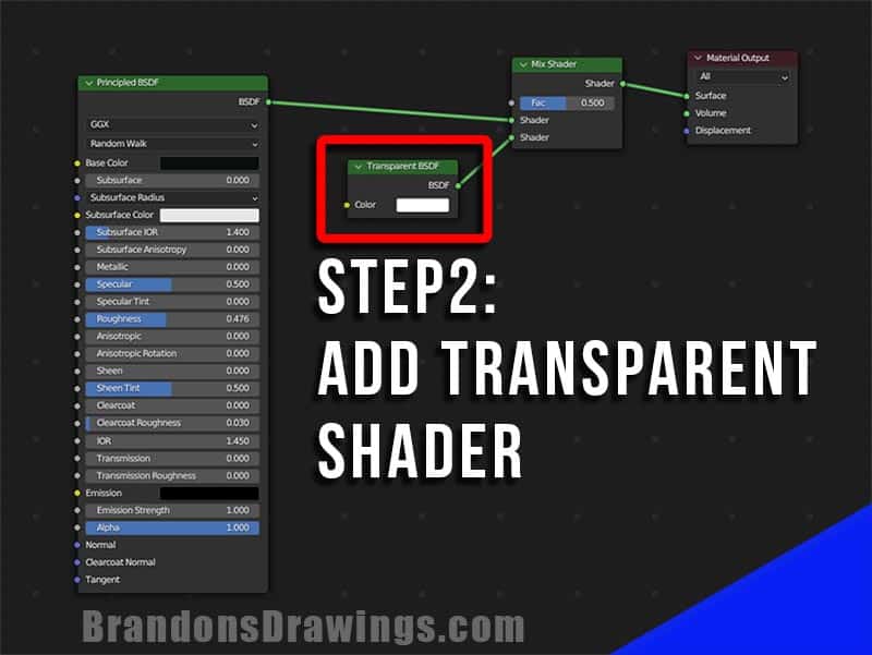
The Mix Shader takes two completed shader outputs and combines them based on the “Factor” setting. By default, the two materials will be blended together in a 50/50 mix. Our object’s material will now be our base material with 50% transparency.
Activate Transparency (If Using Eevee)
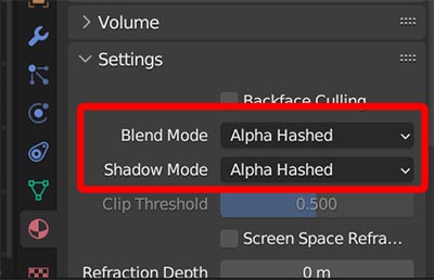
If using Eevee (like I am in this tutorial) you’ll need to activate a setting to allow the transparency for this material to work properly. Go to the Material Properties Tab in the Properties Panel.
Expand the Settings tab inside the material properties. Change the “Blend Mode’ and the “Shadow Mode” to “Alpha Hashed.”
This is a technical setting which instructs Eevee on how to interpret transparent materials. It is not turned on by default.
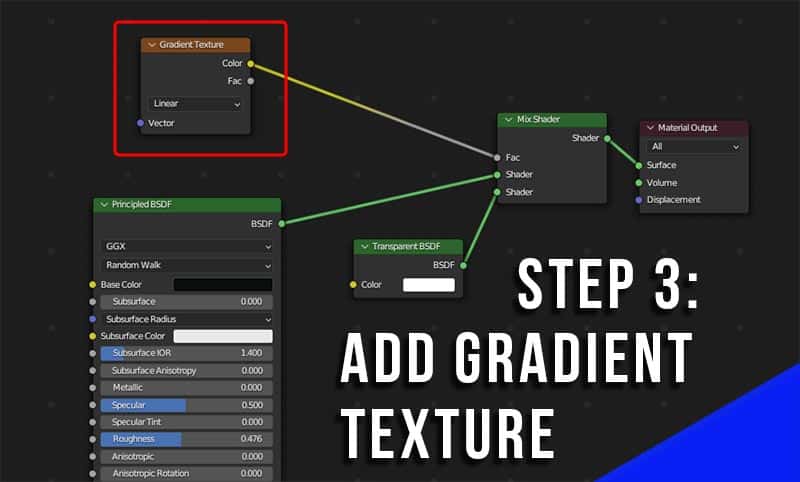
Step 3: Add Gradient Texture
Add a Gradient Texture Node and connect it to the Factor input of the Mix Shader. This tells the Mix Shader to combine the two shaders as a gradient (transitioning smoothly from one to another).
Step 4: Add Color Ramp
Place a color ramp between the Gradient Texture Node and the Mix Shader. This will control the gradient between the two textures.
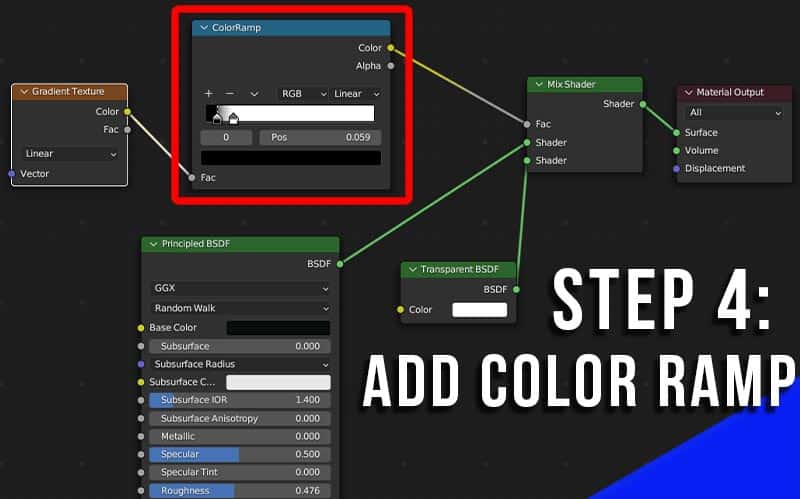
A color ramp defaults to black and white. Where there is black, one texture will be. Where it’s white, another texture will be. The grey between the two represents the transition from the first texture to the second.
Step 5: Mapping and Texture Coordinate Nodes
To give us control over where the gradient is placed, we add a Mapping Node and connect its vector output to the vector input of the Gradient Texture Node.
Then add a Texture Coordinate Node and connect the “Object” output into the vector input of the Mapping Node. This tells Blender we want the mapping of the texture to be based on the shape and location of the object.
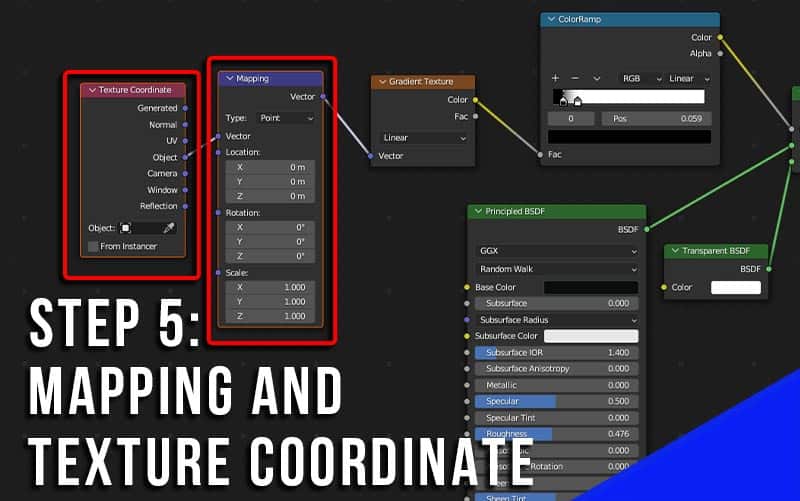
If you’ve watched my introduction to shading series, you know that with Node Wrangler activated, we can click on the Gradient Texture Node and press “Ctrl + T” on the keyboard to automatically add both of these nodes.
The Mapping Node is where we control the location, rotation and scale of the texture. We will eventually have the disintegration effect move across our object by animating the X location value here.
Step 6: Color Ramp Emission
Now we need to give the object some emission which follows the path of the gradient. We will use the emission input of the Principled BSDF shader for this.
This is why, if your material already uses emission, this method of adding a disintegration effect won’t work.
Add a second Color Ramp (or copy the first one). Connect the color output of the Gradient Texture Node to the “Fac” input (factor) of the Color Ramp Node. This time, it is important to use the “Color” output from the Color Ramp Node (not the alpha) and connect it to the Emission input socket of the Principled BSDF Shader.
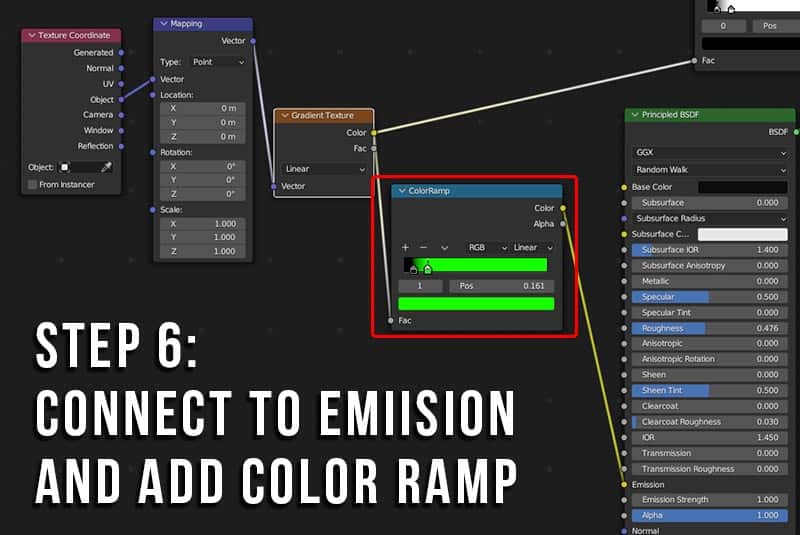
Adjust the stops of the color ramp closer together and choose a color as shown above (it can be any color, but I used green). This will be the color of the emissive parts of the effect.
Step 7: Noise Texture and Mix Node
So far, the emissive part of the transition is in a straight, vertical line. That’s not what we want. We will add some random distortion to this line by placing a Noise Texture Node and a Mix Node between the Texture Coordinate Node and the Mapping Node.
Set it up as shown in the image below. This is mixing noise into the mapping of the gradient, so it’s not a perfectly straight line.
You will have to change the mix type on the Mix Node from the default “Float” to “Color.”
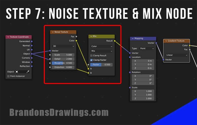
Play around with the scale, detail, roughness and distortion settings on the Noise Texture Node.
The Factor slider on the Mix Node controls how much of the noise is mixed into the gradient.
Sliding it all the way to one side will give zero noise and sliding it in the opposite direction will add noise (the direction depends on which input is plugged into which socket of the Mix Node).
How to Animate the Disintegration Effect
We animate the disintegration effect by applying keyframes to nodes in the nodetree. This assumes you know the basics of how keyframe animation works in Blender.
Here are a few values we can animate to bring the disintegration effect to life.
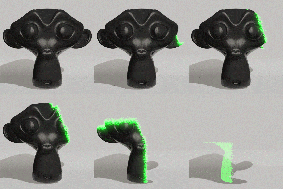
Animate the Location
If we have the material correctly mapped using “Object” in the Texture Coordinate Node, we can animate the effect moving across an object from the Mapping Node.
Go to the frame where we want this animation to start. Move the location value (in the above image it’s the X axis) so the effect moves just barely off the object and the base material is visible on the entire model.
Then place a keyframe on the X axis (or the appropriate axis for your 3D model). To place a keyframe, hover over the value slider in the Mapping Node and press “i” on the keyboard.
Then go to the frame where we want the disintegration effect to finish (maybe 60 frames after it started – that’s what I did). Now slide the location value on the Mapping Node so the disintegration passes entirely over the object. Stop just after the object becomes completely transparent.
Add a second keyframe to the location value by hovering over the value and pressing “i” on the keyboard.
Animate the Noise Mix
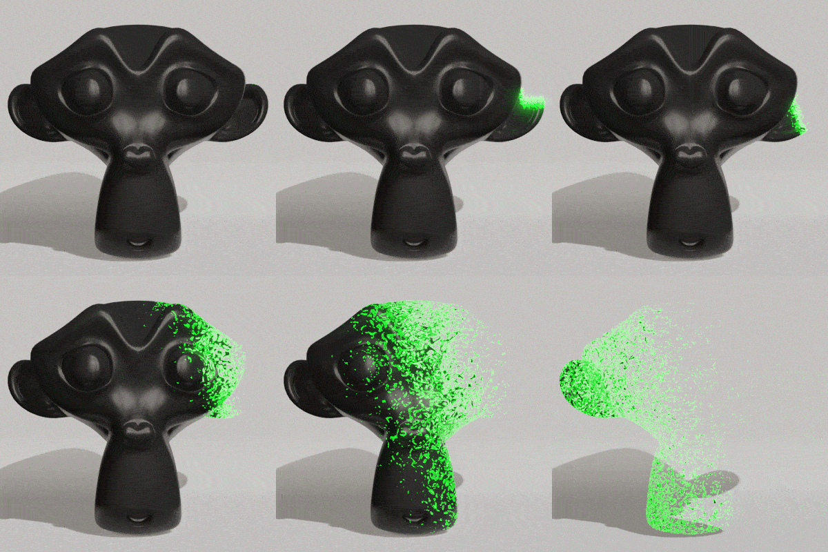
Another value of our disintegration effect we can animate is the amount of noise mixed into the node tree before the Mapping Node. This is done on the Mix Shader, just left of the Mapping Node in the above image.
Try having the effect start small (closer to 1 in this case) and increase it over several frames. This causes the effect to spread out during the animation. This effect can be combined with the first animation method covered above.
Conclusion
I hope this was a useful tutorial. Again, this was intended to accompany the video at the top of this post. It’s a cool effect and the video really breaks it down and explains each step of the process.
Have a look around my site for more Blender topics, become a subscriber on YouTube and join my newsletter for the latest tips. Stay creative!


